Gm Single Wire Alternator Diagram Wiring Diagrams Hubs Gm 1 Wire Alternator Wiring Diagram
On a 2g (but not 1g) ECU pin 92 (note: this pin is incorrectly labeled Ignition switch on some 2g ECU pinout diagrams) goes to the signal grounds of the following engine sensors: manifold diff pressure, engine coolant temp, front O2, rear O2, TPS, volume air flow, and fuel tank diff pressure.
Ellen Scheme Lucas 11ac Alternator Wiring Diagram Pdf Editor

Driving a Mitsubishi is an exciting experience, and having all of the parts operating correctly is essential. An alternator wiring diagram for Mitsubishi vehicles, in particular, can be essential for making sure that everything runs smoothly. This guide should provide you with the information you need to make sure your alternator is wired properly.Alternators are responsible for generating.
Nikko Alternator Wiring Diagram Wiring Digital and Schematic

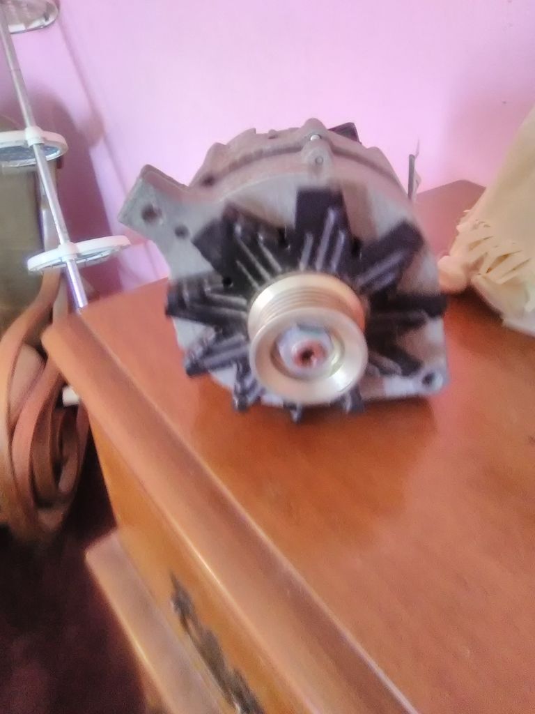
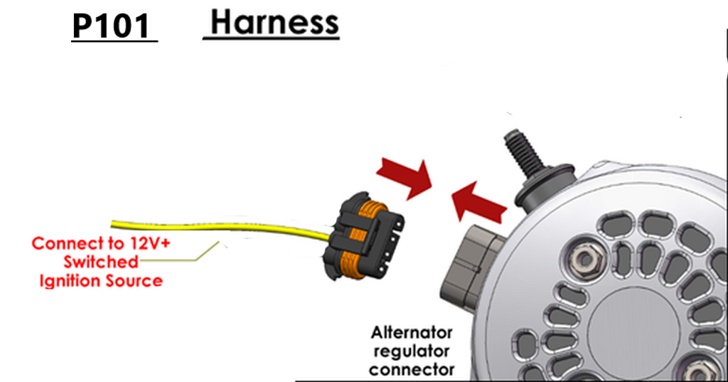
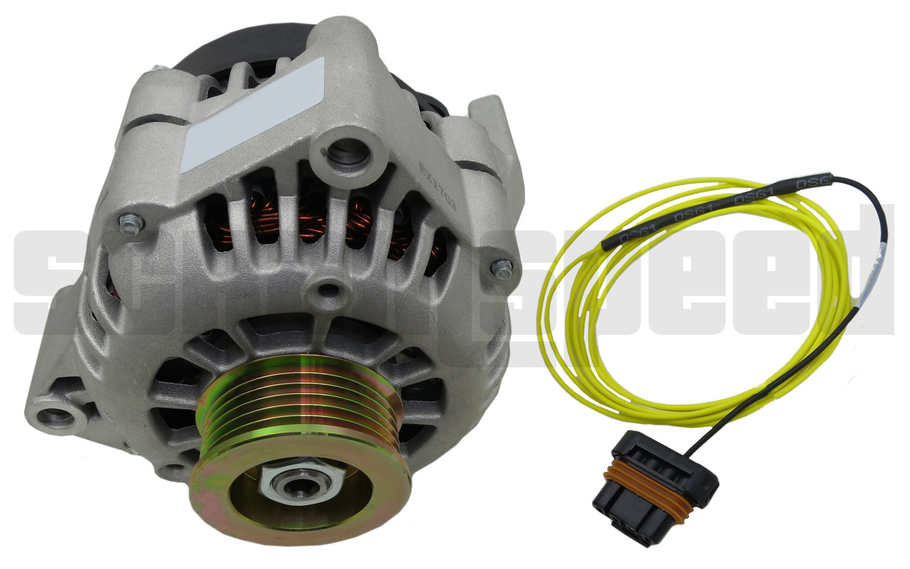
Alternator Wiring for plug HELP, sanity check. 08-27-2020, 09:25 AM. Someone please check my sanity on this. In my 03, I have the original delco alternator 70 amp alternator that has the 2 pin plug with the post for the charge power. One of wires (red, I think) is the exciter wire that will go a switched 12+ power.
Hollie Wires Lucas 3 Pin Alternator Wiring Diagram Toolbox

Connect the wires with a solderless connector to complete the procedure. Make sure the wire is long enough to connect to the same starter solenoid terminal as the positive battery cable and the alternator output wire. Finally, use a solderless ring connection to attach the wire to the terminal. Step 9.
1g Dsm Alternator Wiring Diagram Wiring Diagram Pictures
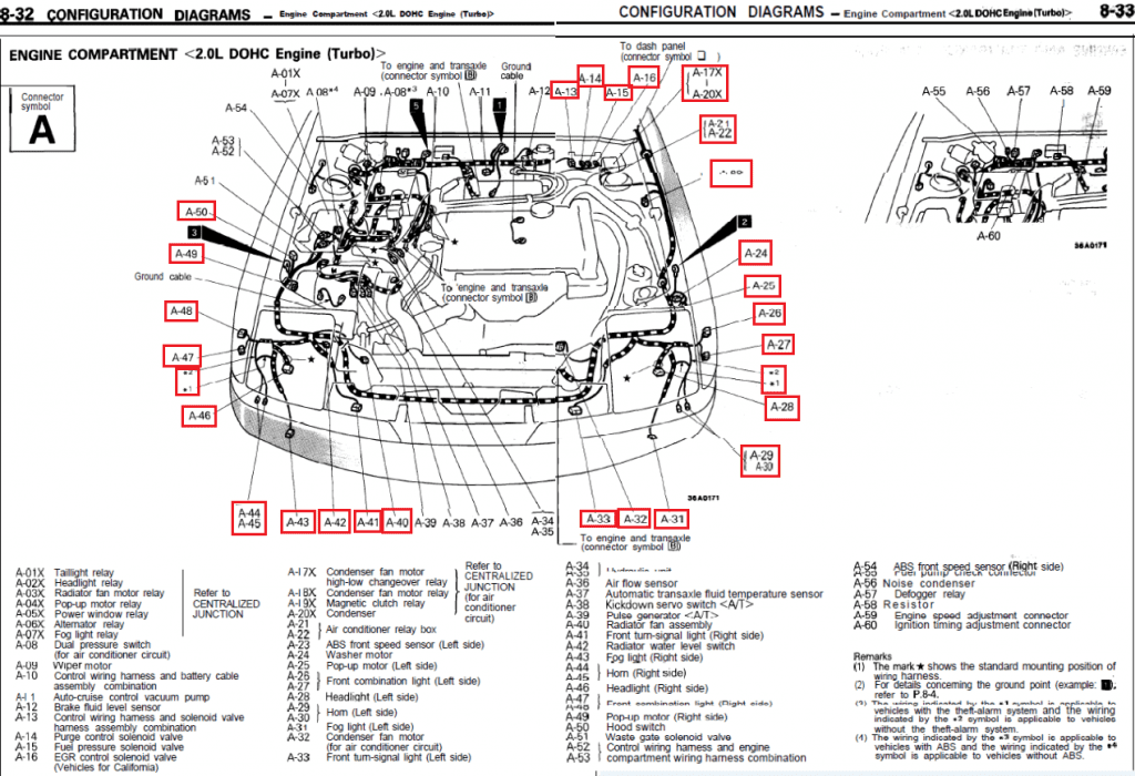
The Mitsubishi 4 pin alternator wiring diagram is a simple and easy-to-follow guide that can help you troubleshoot any problems with your alternator. It shows you where each wire connects to the alternator, so you can quickly identify any loose or damaged wires. The diagram is divided into two sections: the positive and negative terminals.
Si Alternator Wiring Diagram vascovilarinho
Mitsubishi 4 pin alternator wiring diagrams are a critical part of maintaining a reliable electrical system in your vehicle. Whether you're an experienced automotive professional or just someone trying to get their car running again, understanding how the 4 pin alternator works is important to ensure your safety and the longevity of your vehicle's electrical system. Today's vehicles.
Ls1 Alternator Wiring Diagram ubicaciondepersonas.cdmx.gob.mx

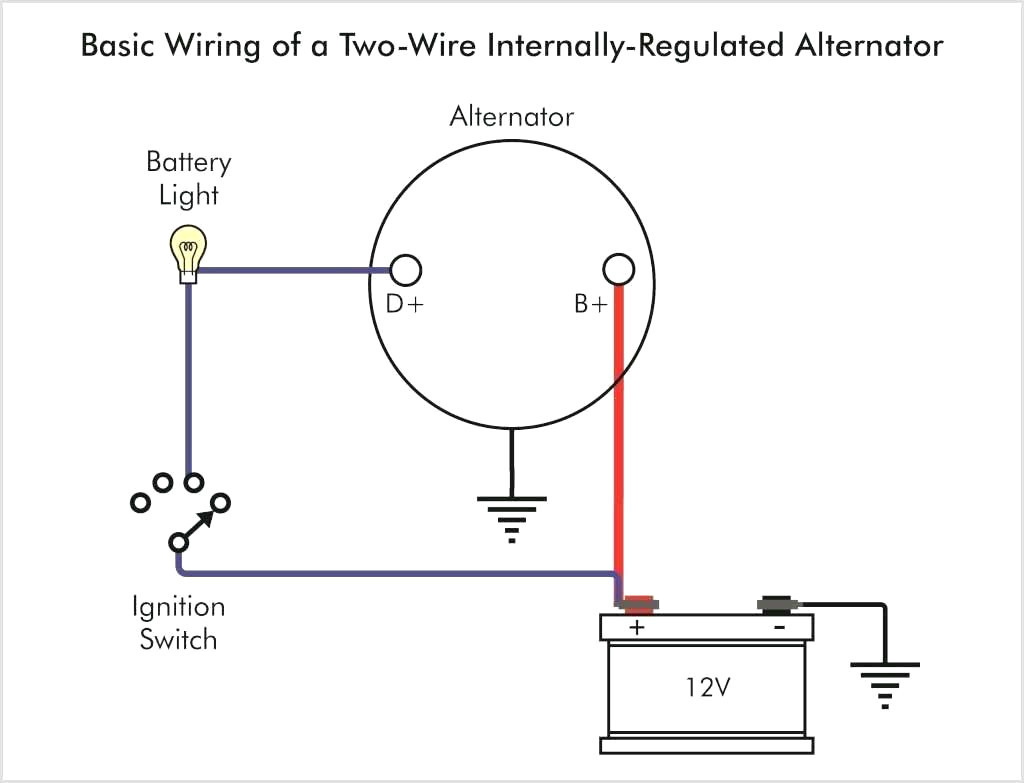
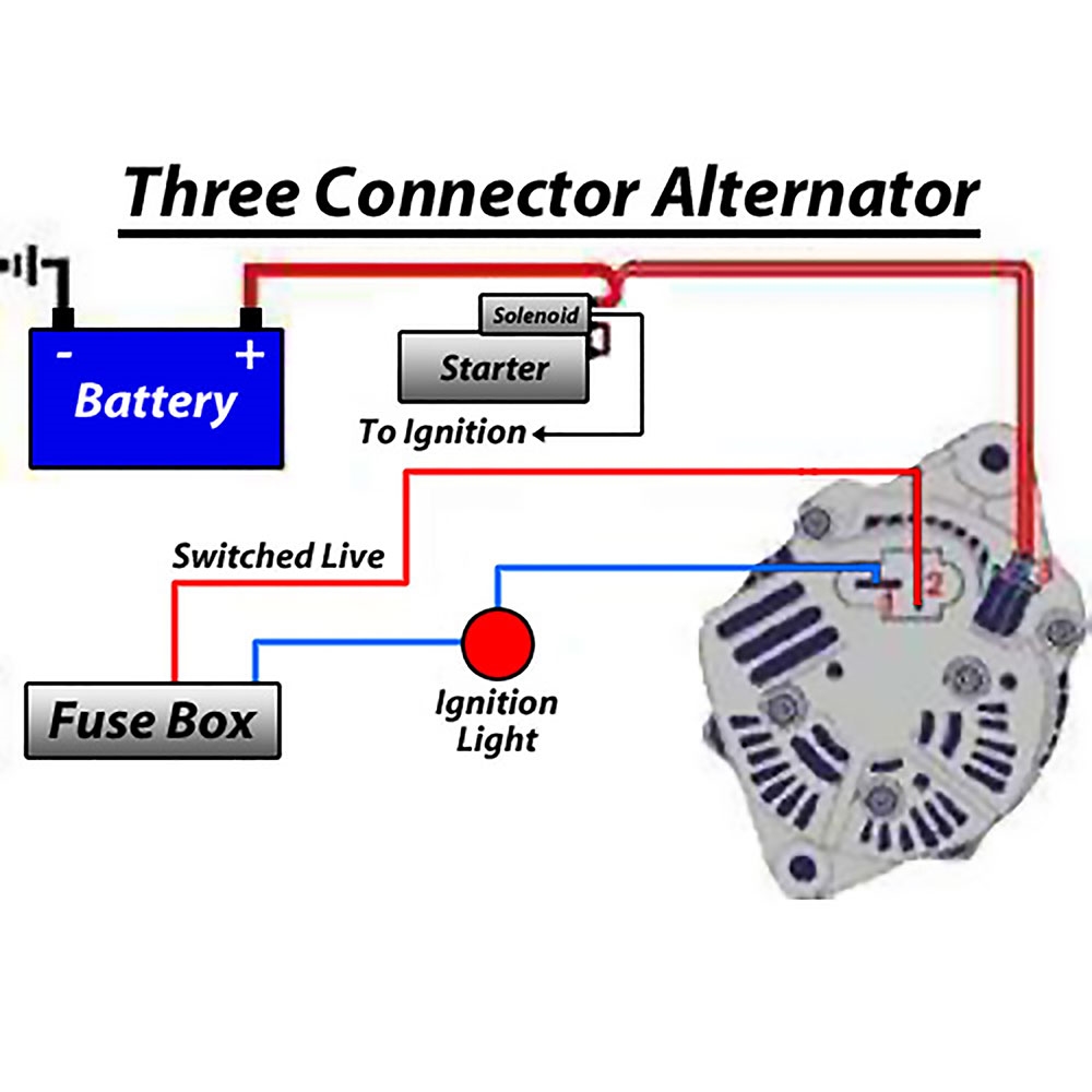
Field or ignition terminal: Allows battery voltage from the ignition to flow to the alternator's field coil during startup. Electronic voltage regulators have been used on many cars since the mid 1970s. 3-Wire Alternator Wiring Diagram. Refer to the diagram below if you're working on three-wire connections.
Leece Neville Alternator Wiring Diagram Prestolite Manual EBooks Leece Neville Alternator
Step 3: Identify the pins and wires on the alternator: Examine the 2 pin alternator and identify the pins and wires. Typically, one pin is labeled "B" for the battery, and the other pin is labeled "S" or "C" for the stator or sense wire. Refer to the wiring diagram for your specific alternator to confirm the pin designations.
Ls1 Alternator Wiring Diagram ubicaciondepersonas.cdmx.gob.mx
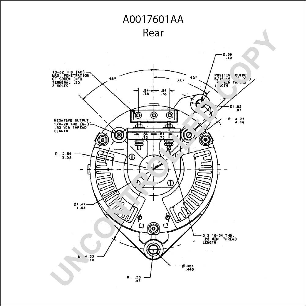
An alternator has four terminals: R, S, S (Ford), and T. The R terminal is the main terminal, and the S and T terminals are the secondary terminals. The Ford terminal is used to connect the alternator to the battery. You can see the following table to check their definitions and notes. TERMINAL.
Delco Alternator Wiring Diagram Cadician's Blog
The Mitsubishi Alternator Wiring Diagram PDF is an electronic document that contains detailed information about your alternator's wiring diagram. It includes color coded wiring diagrams so that you can easily identify each component in the system. The Mitsubishi Alternator Wiring Diagram PDF also includes detailed instructions on how to.
Subaru Alternator Wiring Diagram Wiring Digital and Schematic

Mitsubishi Alternator Wiring Explanation. Hi there , I have mounted a remote car starter , and the chip "knows" the engine started by getting +12V signal from alternator , otherwise will continue to excite the starter forever. this is the last wire I have to discover and connect to remote car start I want to know what each wires do on the.
Mitsubishi 2 Pin Alternator Wiring Diagram Diary Tags
The connection diagram of an alternator shows how the various components are connected to each other and to the vehicle's electrical system. The main components of an alternator include the rotor, stator, rectifier, voltage regulator, and the output terminals. The rotor is the rotating part of the alternator that creates a magnetic field.
Vw Alternator Wiring Diagram Diysive
1035 Data Lane Knoxville, TN 37932 Customer Service Available: Mon. - Fri.: 9am - 430pm 1 (888) MECHMAN
Ross Wiring Mitsubishi 4 Wire Alternator Wiring Diagram

Need Help? Ask a mechanic online, 24 hours a day here: https://tinyurl.com/24-7-mechanicIn this video we'll talk about a 3 wire alternator wiring diagram, ho.
Ls1 Alternator Wiring Diagram ubicaciondepersonas.cdmx.gob.mx
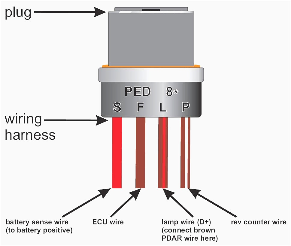
2. The alternator on a 2018 mitsubishi outlander along with many other vehicles has a 4 wire connector going to it. They are labelled as follows: Ground - is self explanatory. Sense - is the input that the alternator is suppose to use to regulate its output voltage with. Lamp - is suppose to allow the alternator to tell the car to turn on the.
Alternator Wiring Diagram For The Battery Alternator Car Floyd Wired

Step 4: Electrical Connections. Connect the brushes of the positive red cable to the alternator's positive terminal. Then, connect the negative terminal of the brush (it may be blue or black) from the rotor field to any part of the alternator's casing (as the ground). Wiring diagram for a 1-wire alternator.